11. Half & Full Adder
Memory was created using flip-flops, which are a form of sequential logic
Earlier, combinational logic was used to perform logical operations
Now, combinational logic will be used to perform addition
However, it will become clear soon that binary addition is effectively a logical operation
11.1. Binary Addition as a Logical Operation
If one wants to add two bits together, how many output bits are needed?
To answer this, consider the possibilities
\(0_{2} + 0_{2} = 0_{2}\)
\(0_{2} + 1_{2} = 1_{2}\)
\(1_{2} + 0_{2} = 1_{2}\)
\(1_{2} + 1_{2} = 10_{2}\)
As one can see, when adding two
1s together, a carry bit is neededThus, when adding two bits together, two output bits are required
In general, when adding two \(n\) bit numbers together, \(n+1\) bits is sufficient to output the correct sum
Remember, adding a bit doubles the number of representable values
Consider the below table showing the result of adding two one bit numbers together
\(A\) and \(B\) are the two one bit numbers
\(S\) is the sum bit
\(C\) is the carry bit
\(A\) |
\(B\) |
\(C\) |
\(S\) |
|
|---|---|---|---|---|
|
|
|
|
|
|
|
|
|
|
|
|
|
|
|
|
|
|
|
Referring to the above table, notice how this is effectively a logical operation
When both inputs are
0, output00When one input is
1, output01When both inputs are
1, output10
As previously discussed, programmable logic arrays can be configured to create any boolean logical function
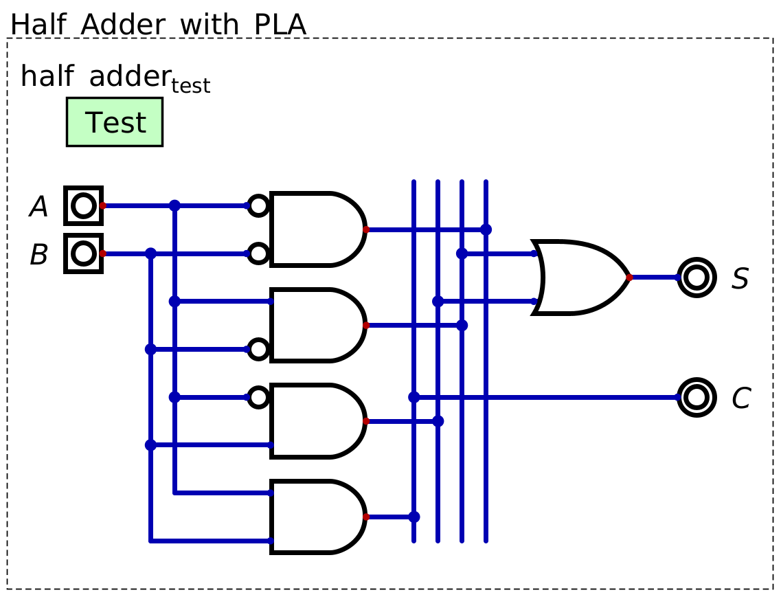
A PLA designed to perform the function of adding two one bit numbers together.
A circuit capable of adding two one bit numbers together is called a half adder
11.2. Half Adder
A programmable logic array is sufficient for building a half adder
However, using programmable logic arrays is a bit like a brute force solution
It is possible to greatly simplify the circuit and use less gates/transistors
Referring to the above table describing the half adder’s functionality, look at each output independently
\(S\) is
1only when either of the input bits are1This is the functionality of XOR
\(C\) is
1only when both input bits are1This is the functionality of AND
In other words, instead of using 5 gates with a programmable logic array, a half adder can be built with only 2 gates
Below is the typical configuration of a half adder
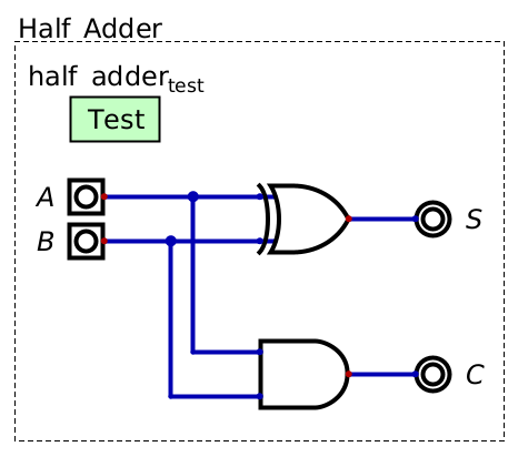
A half adder created with only two gates, namely, an XOR calculating the value of the sum bit (\(S\)), and an AND for calculating the value of the carry bit (\(C\)). This is the typical design of a half adder circuit.
Unfortunately, a half adder is only capable of adding two one bit numbers together
To add numbers with more bits, one may be tempted to chain half adders together
However, this will not work as the carry bit has no way to be accounted for in the next bit’s addition
Think about regular base 10 addition
If the sum of one digit is 10 or more, the 10s value is carried over and included in the sum of the next digit
Thus, the half adder must be modified to incorporate an input of a carry bit
11.3. Full Adder
A full adder is a circuit designed to add binary numbers of arbitrary size
The idea is the same as a half adder, but they provide a way to input carry bits to be accounted for in the sum
Below is a table showing the desired functionality of a full adder
\(A\) |
\(B\) |
\(C_{in}\) |
\(C_{out}\) |
\(S\) |
|
|---|---|---|---|---|---|
|
|
|
|
|
|
|
|
|
|
|
|
|
|
|
|
|
|
|
|
|
|
|
|
|
|
|
|
|
|
|
|
|
|
|
|
|
|
|
|
|
|
|
|
|
|
|
Again, observe each output independently and find the patterns of when the output should be active
\(S\) is high only when one or three of the inputs are
1; when an odd number of inputs are1This is, again, XOR’s functionality
Remember from earlier, XOR can be used as a way to check even/odd
\(C_{out}\) is
1when any combination of two or more input bits are1If \(A\) and \(B\) are both
1Or if \(A\) and \(C_{in}\) are both
1Or if \(B\) and \(C_{in}\) are both
1Or if \(A\), \(B\), and \(C_{in}\) are all
1
\(C_{out}\) can be simplified to check if
\(A\) and \(B\) are both
1Or if the sum of \(A\) and \(B\) is
1and \(C_{in}\) is1Note, if the sum of \(A\) and \(B\) is
1, then at least one of the inputs was1
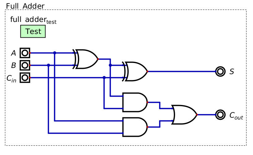
A full adder, which is capable of including an inputted carry bit in the summation of the inputs.
11.3.1. Adding Larger Numbers
The full adder design scales to arbitrary size to enable the addition of large binary numbers
This is achieved by chaining multiple full adders together
A full adder is required for each bit
Each full adder’s \(C_{out}\) is fed into the next significant bit’s full adder’s \(C_{in}\)
Below is an example of full adder capable of adding two four bit numbers together
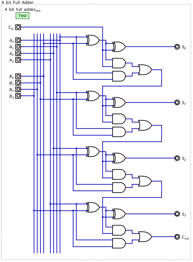
A four bit full adder. Notice how each output bit is summed with it’s own full adder and each full adder’s \(C_{out}\) is fed back into the full adder at the next significant bit.
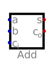
11.3.2. Full Adder Symbol
Adders are represented as a labeled box
Within Digital, adders can be edited to allow for arbitrary input sizes
11.4. For Next Time
Check out the
Half Adder with PLAschematic for DigitalCheck out the
Half Adderschematic for DigitalCheck out the
Full Adderschematic for DigitalCheck out the
4 Bit Full Adderschematic for DigitalRead Chapter 2 Section 3 of your text
2 pages