15. Seven Segment Displays
Binary values from the data bus have been readable through Digital’s output components
However, base 10 is preferable when viewing numbers
Further, the data on the bus is always changing
Sometimes output should persist
Not all data on the bus needs to be output
An output register will be used to improve system outputs
Seven segment displays will be used as the mechanism for displaying base 10 numbers
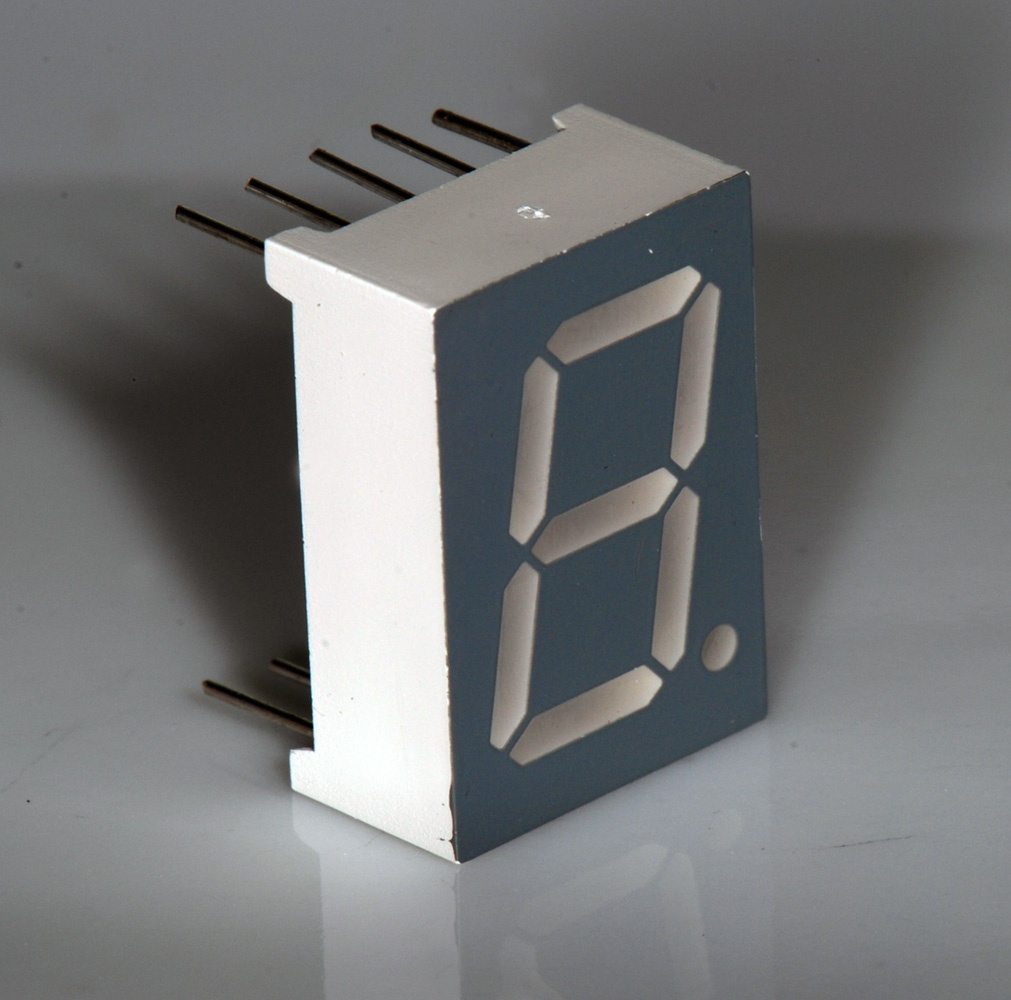
A common seven segment LED display. By turning different segments of the display on/off, different values can be visually represented.
15.1. Seven Segment Display
Seven segment displays are made up of seven toggleable segments
By turning these segments on/off, different symbols can be represented
A total of \(2^{7}\) (\(128\)) unique patterns can be represented
Although not all would necessary be meaningful
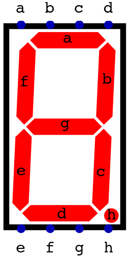
A seven segment display from Digital with the eight inputs and corresponding segments labelled. When a high signal is applied to an input, the respective segment would turn on.
Although they are called seven segment displays, it’s common to have an eighth segment representing a decimal point
Which explains why these components have eight inputs
Thus, there is actually a total of \(2^{8}\) (\(256\)) unique patterns
Since a one signal controls one segment, eight signals are required to control the eight total segments
Animation of each of the eight inputs on a seven segment display being activated. As each input is made high, the corresponding segment turns on.
One can think of these eight signals as 8 bits/1 byte
But, it is important to remember that the bit patterns is an encoding
Some decoding is needed to derive meaning
For example, assume a byte is used to control the seven segment display such that
ais the least significant bitEach bit in the byte controls one segment
hgfedcba
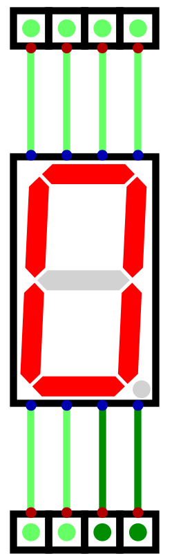
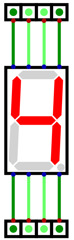
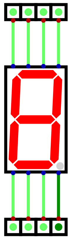
The number 9 is
0b00001001However, this bit pattern would display the following
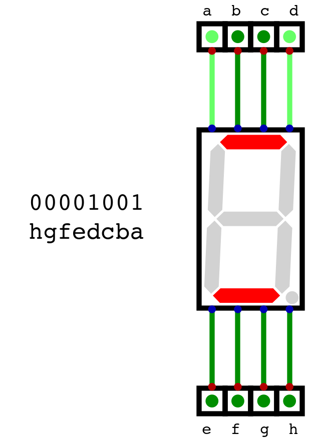
The state of a seven segment display when the inputs are set to 0b00001001, ordered such that a is the least
significant bit and h is the most significant.
In other words, the byte representing 9 as an integer has an entirely different meaning when used for the display
0b00001001is only an encoding
15.2. Binary Numbers to Decimal for a Seven Segment Displays
A system to convert the binary numbers to their respective seven segment display patterns needs to be developed
As discussed, a single byte can be used for each seven segment display
Here, the display’s
ainput will be the least significant bit, andhwill be the most significantThis ordering is a design decision and not a requirement
Below is a table showing each decimal number’s bit pattern for the seven segment display
Decimal |
Binary |
Display Pattern |
Display Hex |
Output |
|
|
|
|
|
|
|
|
|
|
|
|
|
|
|
|
|
|
|
|
|
|
|
|
|
|
|
|
|
|
|
|
|
|
|
|
|
|
|
|
|
|
|
|
|
|
|
|
|
|
|
|
|
|
|
|
|
|
|
|
Note
One may have noticed that the seven segment display pattern for the number seven is the binary number seven.
This is in no way meaningful, and is a consequence of the arbitrary bit ordering to the inputs, but an interesting observation nonetheless.
Consider, however, the number 10, which is easily representable in binary with 8 bits
One cannot represent this number with a single digit
Although hexadecimal can be used, and an
Acan be displayed on a seven segment display, this misses the pointThe goal is to show decimal numerals
And further, the same issue arises with hexadecimal numbers once the number 16 is hit
The system being designed can represent eight bit numbers
A total of 256
0 – 255
Thus, a total of three digits are required for this system’s output
Fortunately, there is a simple way to deal with this
Use three displays and three bytes for an 8 bit integer
Map a single 8 bit integer to three 8 bit patterns, one for each of the three displays
In other words, the number 10 maps to a byte for 0, a byte for 1, and another byte for 0
0b00001010maps to0b0011111111,0b00000110, and0b0011111111
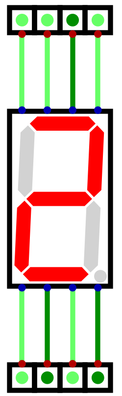
Below is an example of displaying the number 123
0b01111011maps to0b00000110,0b01011011, and0b01001111
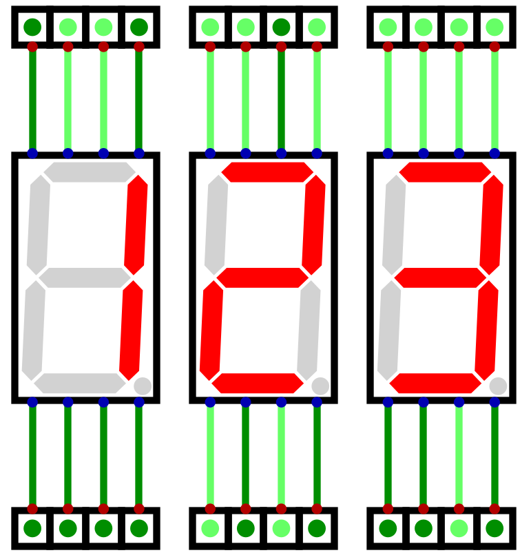
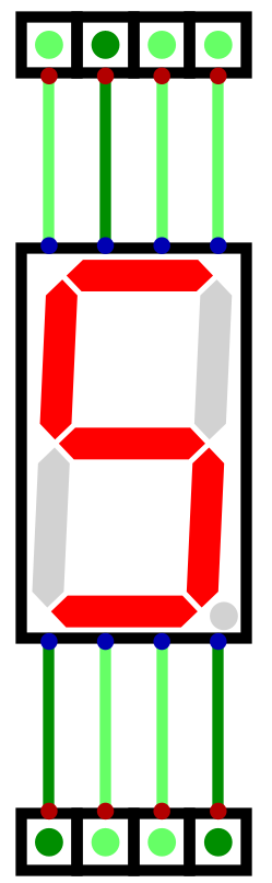
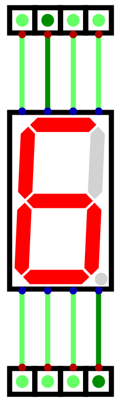
Three seven segment displays showing the number 123. The number 123, represented in binary as 0b01111011 must
map to three bytes to display 1, 2, and 3. These bytes would be 0b00000110, 0b01011011, and 0b01001111
respectively.
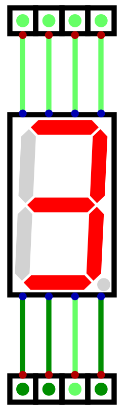
Further, since the system works with two’s complement numbers, negative numbers should be displayable on the output
Numbers -128 – 127
This is achieved with a forth display that would only ever activate the
ginput, when necessaryThis forth, leftmost display would only activate
gwhen showing a negative numberPositive numbers would have nothing displayed on this forth display
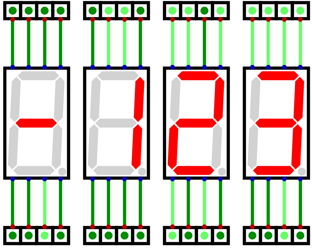
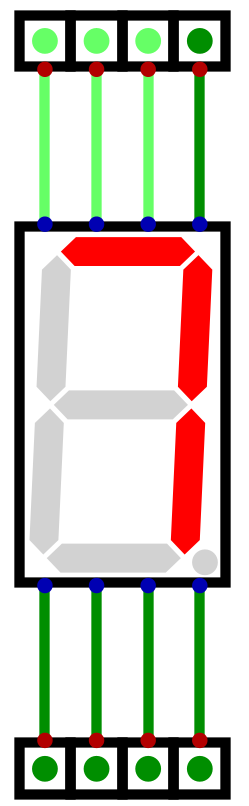
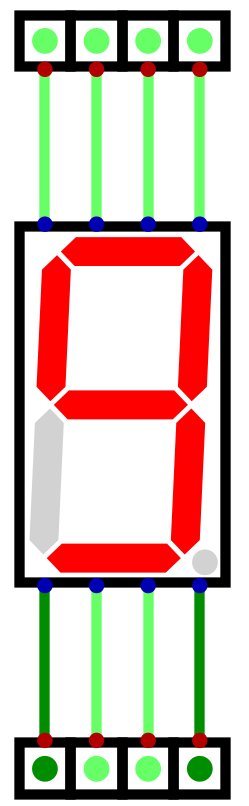
Four seven segment displays showing the twos complement number -123 (0b10000101). The left most display in this
configuration would only ever be used to show the negative sign, when appropriate.
15.2.1. Programmable Logic Arrays and Look Up Tables
As discussed earlier in the semester, Programmable Logic Arrays (PLAs) can be used to create any logical mapping
Can map any binary input to a binary output
Thus, they are ideal for mapping the system’s binary numbers to their seven segment display patterns
Unfortunately, however, they scale very poorly with input size and become very difficult to work with
They scale exponentially
Below is an example of a PLA mapping four bits to only the least significant digit’s seven segment display pattern
Two digits would be required to display all possible 4 bit integers
For simplicity (and sanity), only the one digit was included
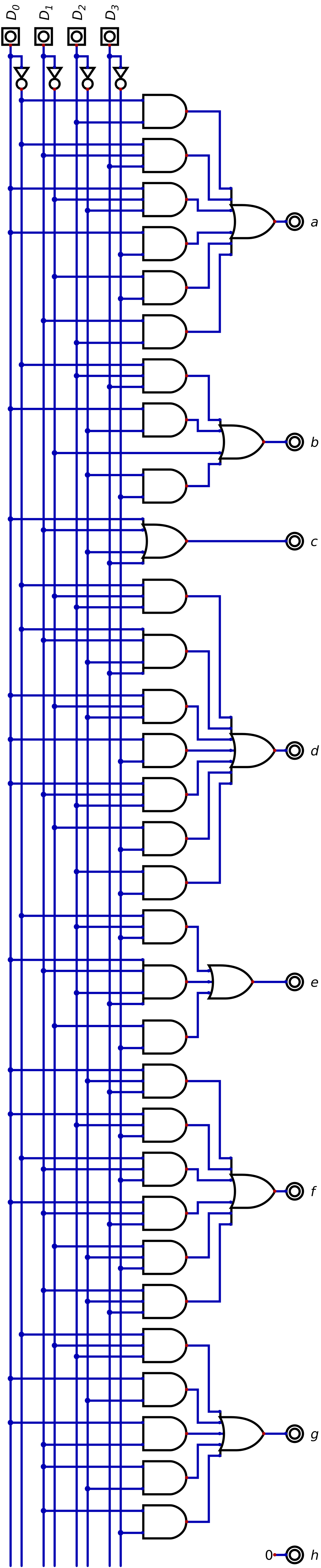
Programmable logic array mapping a 4 bit binary number to a seven segment display pattern for only the least significant digit.
A PLA for all three output bits for an 8 bit number would be markedly larger and much more difficult to work with
Fortunately, as discussed earlier in the semester, Look Up Tables (LUT) can be used to simplify such functionality
In fact, one can edit the LUT easily to enter bit patterns by hand
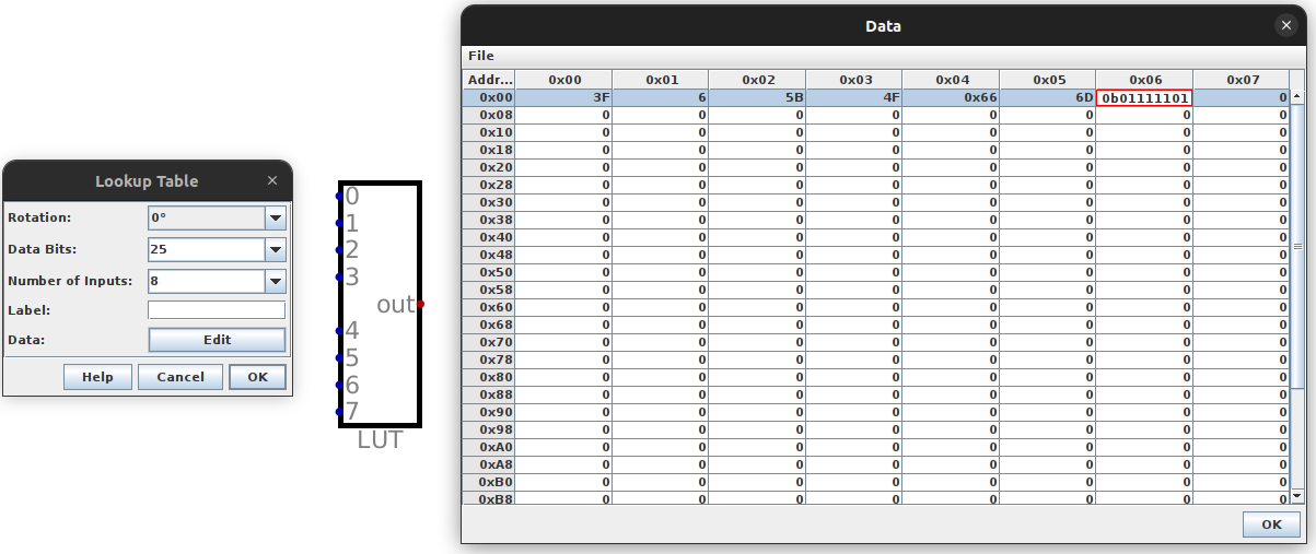
Editing a Look Up Table within Digital
A LUTs contents can be saved to a file, which would produce something like below
Note that the values here are in hexadecimal, not binary
Further, this is far from complete for the 8 bit, 3 digit display
v2.0 raw
3f
6
5b
4f
66
6d
7d
Treating the LUT as a map/dictionary, the key is the row number, and the value is the contents of that row
In the above example, the “key” 3 maps to the “value”
4fThe 3rd row (starting at 0) contains
4f
To make things even easier, one can even import a hex file to the LUT
This way, there is no need to enter all 256 patterns by hand
Instead, the hex file can be generated programmatically
15.3. Using a LUT to Map Numbers to Seven Segment Display Patterns
Since the system is 8 bit, the LUT will be used to decode an 8 bit number into the three digit output
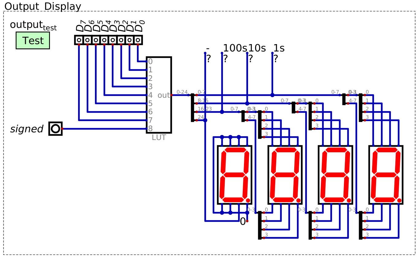
Look up table for decoding an 8 bit binary number into a pattern for a seven segment display to represent a three digit decimal number. This design can display both unsigned and signed (two’s complement) binary numbers, depending on the state of the “signed” signal. The left most seven segment display is only used to display a negative sign, when necessary. This image includes “probes” labelled -, 100s, 10s, and 1s for testing purposes, but are not necessary.
The LUT takes 8 input lines representing an 8 bit number
Additionally, the LUT will have one additional input line to specify if the number is signed
If the number is two’s complement
This will be discussed in greater detail below
Thus, the LUT will have a total of 9 input signals
The LUT would map these input signals to the corresponding seven segment display patterns for the output
For example, the number
0b10101010would map to the patterns to display the decimal number 170The number
0b10101010would map to the pattern for -086 if the \(signed\) signal was high
Since each digit uses 8 bits for its display pattern, and there are three digits, a total of 24 bits are needed
However, there is an additional output signal needed to control the negative sign
Notice in the design that only one line from the LUT is connected to the left most seven segment display
Specifically, the line is connected directly to segment
gof the display, which would be the negative sign
Thus, there is a total of 25 output bits
With the design used here
The least significant 8 bits of the 25 correspond to the least significant seven segment display
The most significant bit controls the negative sign
15.3.1. Creating Seven Segment Display Patterns
A Python script will be used to generate the hex file to be loaded into the LUT
A series of constants for each bit pattern will be created
Notice that these constants are added to a list
Within this list, the bit pattern for
Xis found in indexX
17ZERO        = 0b00111111  # 0x3F
18ONE         = 0b00000110  # 0x06
19TWO         = 0b01011011  # 0x5B
20THREE       = 0b01001111  # 0x4F
21FOUR        = 0b01100110  # 0x66
22FIVE        = 0b01101101  # 0x6D
23SIX         = 0b01111101  # 0x7D
24SEVEN       = 0b00000111  # 0x07
25EIGHT       = 0b01111111  # 0x7F
26NINE        = 0b01101111  # 0x6F
27DIGITS = [ZERO, ONE, TWO, THREE, FOUR, FIVE, SIX, SEVEN, EIGHT, NINE]
15.3.1.1. Unsigned Integers
To create the 25 bit output patterns, two bitwise operators will be used
Bit shifting
Move bits to the left/right in a binary pattern
For example, consider shifting a binary pattern 4 bits to the left
0b0101 << 4results in0b01010000
Bitwise
ORPerform
ORon each bit in two bit patternsFor example
0b11001100 | 0b11110000results in0b11111100
Further, given some number, it is possible to obtain the each individual digit with basic arithmetic
Divide the number by the desired digit’s place value, then mod 10
For example, consider the number
123123 / 100 = 1,1 % 10 = 1, therefore the 100s place is1123 / 10 = 12,12 % 10 = 2, therefore the 10s place is2123 / 1 = 123,123 % 10 = 3, therefore the 1s place is3
With this, the idea is to take each 8 bit number, obtain each place’s digit’s pattern, and left shift where necessary
This is best explained with an example
Consider the number 123 — each digits pattern is as follows
1 —
000001102 —
010110113 —
01001111
Bit shift the 8 bits for the 100s number 16 bits to the left, shift the 10s 8 bits to the left, and the 1s shift 0
Each pattern would then be as follows (leading
0s and spaces are included for visual clarity)1 —
00000110 00000000 000000002 —
00000000 01011011 000000003 —
00000000 00000000 01001111
Finally, performing bitwise
ORon these patterns would result in the full pattern for the 8 bit number123 —
00000110 01011011 01001111
Note that the most significant, 25th bit, is not needed here as the number is positive
If a leading bit is not explicitly set to
1, it will be0
Further, in the below code, bit shifting the 1s digit to the left 0 bits has no functional purpose
It is included for consistency
52unsigned_three_digit_patterns = []
53for i in range(0, 256):
54    hundreds_pattern = DIGITS[(i//100) % 10] << 16
55    tens_pattern = DIGITS[(i//10) % 10] << 8
56    ones_pattern = DIGITS[(i//1) % 10] << 0
57    three_digit_pattern = hundreds_pattern | tens_pattern | ones_pattern
58    unsigned_three_digit_patterns.append(three_digit_pattern)
15.3.1.2. Signed Integers
The same idea is used for the signed integers, but following the two’s complement pattern
0b00000000–0b011111111corresponds to integers 0 – 1270b10000000–0b11111111correspond to integers -128 – -1
For all patterns representing negative numbers, the most significant, 25th bit, is set high
To represent the negative sign
A single
1would be bit shifted to the left 25
68signed_three_digit_patterns = []
69for i in range(0, 128):
70    hundreds_pattern = DIGITS[(i//100) % 10] << 16
71    tens_pattern = DIGITS[(i//10) % 10] << 8
72    ones_pattern = DIGITS[(i//1) % 10] << 0
73    three_digit_pattern = hundreds_pattern | tens_pattern | ones_pattern
74    signed_three_digit_patterns.append(three_digit_pattern)
75
76for i in range(-128, 0):
77    negation_pattern = 0b1 << 24
78    hundreds_pattern = DIGITS[(abs(i)//100) % 10] << 16
79    tens_pattern = DIGITS[(abs(i)//10) % 10] << 8
80    ones_pattern = DIGITS[(abs(i)//1) % 10] << 0
81    three_digit_pattern = negation_pattern | hundreds_pattern | tens_pattern | ones_pattern
82    signed_three_digit_patterns.append(three_digit_pattern)
Since that there are two sets of numbers to decode (unsigned and signed), each set can be stored in their own LUT
One LUT has all the unsigned 8 bit integer patterns
The other LUT has all the signed 8 bit integer patterns
A control signal and multiplexer can be used to select which type of integer to display
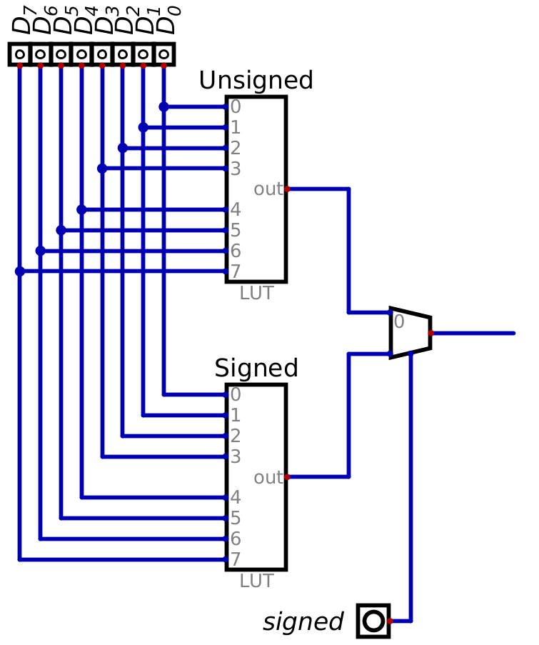
Two look up tables, each storing their respective 8 bit unsigned/signed integer patterns for seven segment displays. A signal called \(signed\) controls a multiplexer which allows for selecting which integer type (unsigned/signed) is actually output to the seven segment displays.
However, the same functionality can be achieved with a single LUT with an additional input signal
8 bits represent the number, and the 9th input would be the \(signed\) control line
Remember, with 9 input bits, a total of \(2^{9}\) (\(512\)) unique values can be indexed
Thus, the first 256 numbers could be unsigned integers, and the following 256 could be signed
In other words
0b0 00000000–0b0 11111111store the unsigned integers0b1 00000000–0b1 11111111store the signed integers
One could think of it as the 9th bit selecting which block of 256 values to index
In the same way as the control signal and multiplexer would select which LUT’s pattern is output
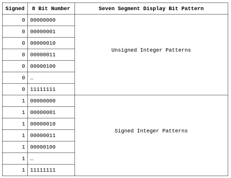
Table representing how the nine input signals on the look up table map to the 512 unique display patterns. When the \(signed\) control signal is low, the 8 bit binary number input would map to the 256 unsigned integer patterns in 0 – 255. When the \(signed\) control signal is high, the 8 bit binary number maps the 256 signed integer patterns in 256 – 512.
Notice how, with this configuration, the meaning of the input signals differ
The first 8 bits represent some binary number
The ninth bit is not part of the binary number, but represent a control signal
15.3.1.3. Saving to a Hex File
Finally, the lists of patterns are saved to a hex file that can be loaded into the LUT
The
v2.0 rawis necessary for Digital to parse the hex filesThe first 256 patterns are the unsigned integer patterns
The following 256 patterns are the signed integers
 97with open("seven_segment_patterns_for_look_up_table.hex", "w") as hex_file:
 98    hex_file.write("v2.0 raw\n")
 99    hex_file.writelines(f"{hex(pattern)}\n" for pattern in unsigned_three_digit_patterns)
100    hex_file.writelines(f"{hex(pattern)}\n" for pattern in signed_three_digit_patterns)
Once generated, the hex file can be loaded into the LUT
Below are examples of using the LUT to decode the signal
0b10101010as an unsigned and signed integer
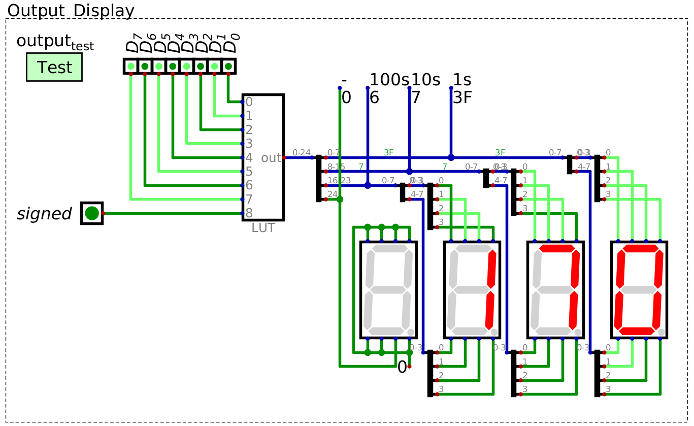
LUT decoding the binary pattern 0b10101010 to the unsigned decimal number 170``.
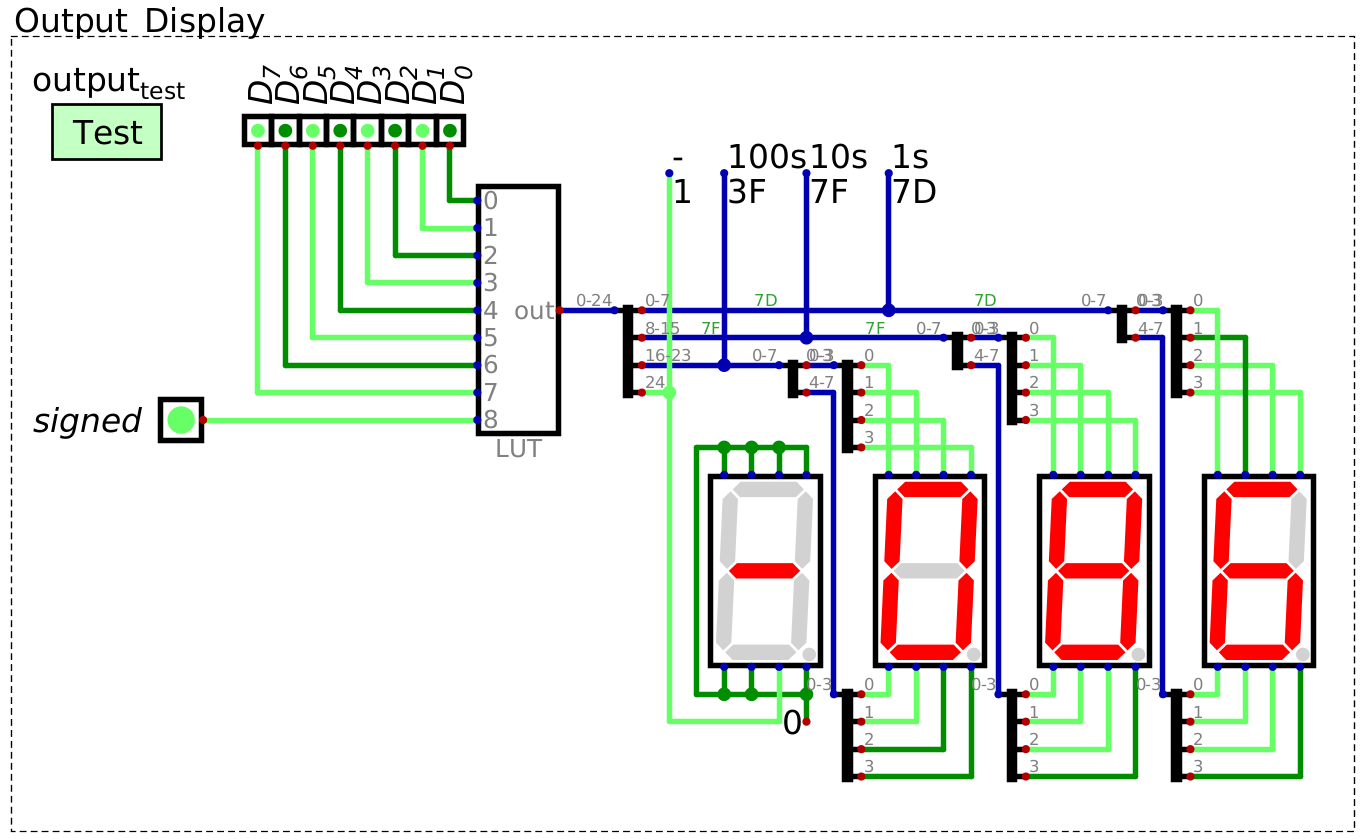
LUT decoding the binary pattern 0b10101010 to the signed, two’s complement decimal number -86. The LUT is
outputting the two’s complement pattern since the 9th input bit, which acts as a control signal for signed integers,
is set to high.
15.4. For Next Time
Something?