4. Transistors
When talking about electricity and semiconductors, things can get rather nuanced and complex
However, the level of detail covered for this topic will be kept appropriate for the course content
As such, certain analogies and ideas will be used that are technically inaccurate, but sufficient for our needs
4.1. Symbols
For this course, software called Digital will be used to create digital circuits
There are a number of symbols representing components that will need to be understood
Although some of you may be familiar with electronic component symbols, there are some things to note
Certain components have different symbols depending on their context
Some components have different symbols in different regions of the world
When using Digital
An up arrow is used to signify a positive charge
A single horizontal line represents ground — something with no charge; neutral
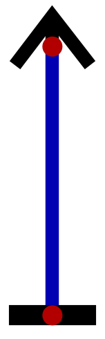
Screenshot from Digital of a positive charge (up arrow) connected directly to ground (horizontal line).
A single horizontal line is common within computer architecture and is the symbol found in Digital
There are other common symbols for ground depending on the context of how it is used
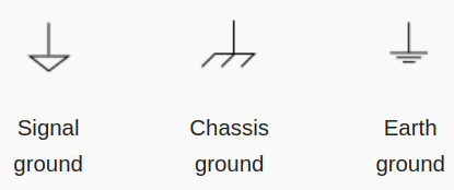
Examples of three commonly used ground symbols. These have slightly different meanings, but all ultimately signify something with a neutral charge.
In the above example, a voltage source was connected directly to ground
In practice, this is a bad idea as that could cause damage and injury
Current would be too high
A resistor, for example, could be added to the circuit to limit its current
Below is an example of the simple circuit containing a resistor
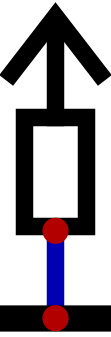
Screenshot from Digital of a positive charge (up arrow) connected to ground (horizontal line) through a resistor (box).
In North America, a sawtooth symbol is used to represent a resistor, but elsewhere in the world it is typically a box
Like in the above figure
Digital was not made in North America, thus, it makes use of the box symbol
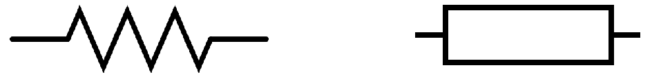
Left — Typical symbol for a resistor in North America. Right — Typical symbol for a resistor outside North America.
One of the commonly seen symbols for transistors are actually only for a specific, but common type of transistor
Bipolar Junction Transistors (BJT)
The transistors available within the simulator Digital are Metal-Oxide-Semiconductor Field-Effect Transistors (MOSFET)
These transistors are common within computers
The symbol used in this course for transistors will be of MOSFET transistors
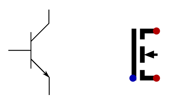
Left — Symbol for a Bipolar Junction Transistor (BJT). Right — Symbol for a Metal-Oxide-Semiconductor Field-Effect Transistor (MOSFET).
4.2. Transistors
Transistors may be one of the most important inventions/discoveries in human history
Bardeen, W. Brattain, and W. Shockley got the 1956 Nobel Prize in Physics for creating the first transistor
Transistors are semiconductor devices
Not strictly a conductor or insulator
Can control the conductive properties of the component
Note
The details on how transistors physically work is outside the scope of this course. For those interested, Ben Eater have two videos describing, at a high-level, how they work.
Transistors perform simple tasks, but are critically important for our everyday lives
Typically, transistors are used for signal amplification or as a switches
For this course, the focus will be on transistor’s ability to be used as a switch
As already discussed, there are several kinds of transistors, but for this course, the focus will be on MOSFET
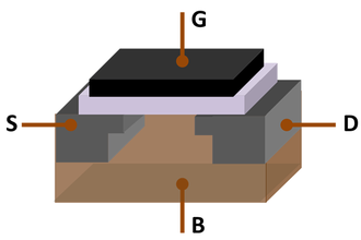
Three-dimensional model of a Metal-oxide-semiconductor field-effect transistor (MOSFET). S — source, D — drain, G — gate, and B — body of the transistor. The source, drain, and gate have terminals to connect to a circuit.
Note
Within the context of digital circuits, it is common to refer to signals as 0s and 1s. The use of 0
and 1 do not signify a specific voltage, but instead 0 means a relatively low voltage and 1 means a
relatively high voltage.
Below is an image of an N-channel MOSFET
This transistor can act as a switch for a signal to travel from the source to the drain
With this type of transistor, the switch is closed (on) when a positive charge is applied to the gate terminal
This would allow the signal to travel from the source to the drain
The signal at the source is arbitrary
The switch would be closed (off) is no positive charge is applied to the gate
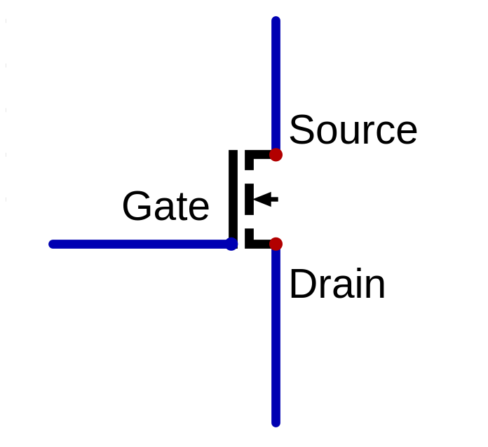
N-channel MOSFET as a switch. The switch is “on” when a positive charge is applied to the gate terminal, allowing a signal to travel from the source to the drain. If no positive charge is applied to the gate, the switch is “off”, not allowing a signal to pass through the transistor.
P-channel MOSFETs exist, which act similar to N-channel, but turn “on” when no positive charge is applied to the gate
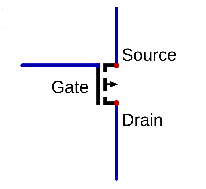
P-channel MOSFET as a switch. The switch is “on” when a negative charge is applied to the gate terminal.
Note
For the most part, N-channel MOSFET transistors will be used in this course.
Below is a circuit with an N-channel MOSFET acting as a switch on some signal that is always on (
1)There are several components to note
N-channel MOSFET
Voltage source providing a signal for the source
A current limiting resistor and ground connected to the drain
A toggleable square button connected to the gate labelled \(switch_{a}\)
Allows for changing the state of the signal applied to the gait when running a simulation
These are called inputs within Digital
A circle to read circuit output labelled \(switch_{o}\)
Allows for easily observing the signal at some point in the circuit
These are called outputs within Digital
A box called “Test” labelled \(switch_{tests}\)
These are where unit tests are written for the circuit
These will be discussed in more detail later
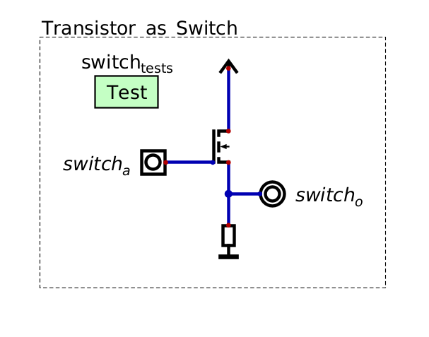
Screenshot of a circuit created in Digital showing an N-channel MOSFET as a switch.
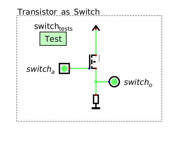
When no positive charge (a signal of
0) is applied to the gate, the transistor does not allow a signal to passThe output of this circuit in this state is therefore a signal of
0
Screenshot of a circuit created in Digital showing an N-channel MOSFET as a switch. Here, the switch is off,
therefore the output of the circuit is 0.
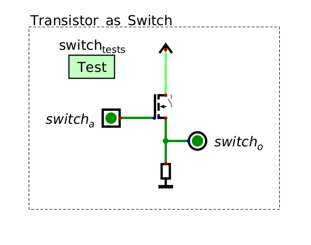
When a positive charge (
1) is applied to the gate, the transistor allows the signal at the source (1) to passTherefore, the output of the circuit in this state is
1
Screenshot of a circuit created in Digital showing an N-channel MOSFET as a switch. Here, the switch is on,
allowing the 1 from the source to pass to the output.
Although this example may seem silly, remember that the actual signal at the source is arbitrary
In the above example, the signal at the source was always set to
1
Further, they become more interesting when combined with additional transistors in clever ways
4.3. For Next Time
Check out the
transistors as a switchschematic for DigitalRead Chapter 3 Section 2 of your text
6 pages