16. Output Register
The look up tables provides a simple way to convert binary numbers to their seven segment display patterns
Now, a register will be incorporated into the design to provide control over which data is being output to the display
16.1. Output Module
With the LUT and seven segment display configuration, it is possible to output values from our system
However, like with the memory module, there needs to be a way to separate the data to be output from the bus
Otherwise, the display would show whatever is currently on the bus
Thus, like with the memory module, a register will be used to store the value that is of interest
This register will be called the output register
The seven segment displays will always show the contents of the output register
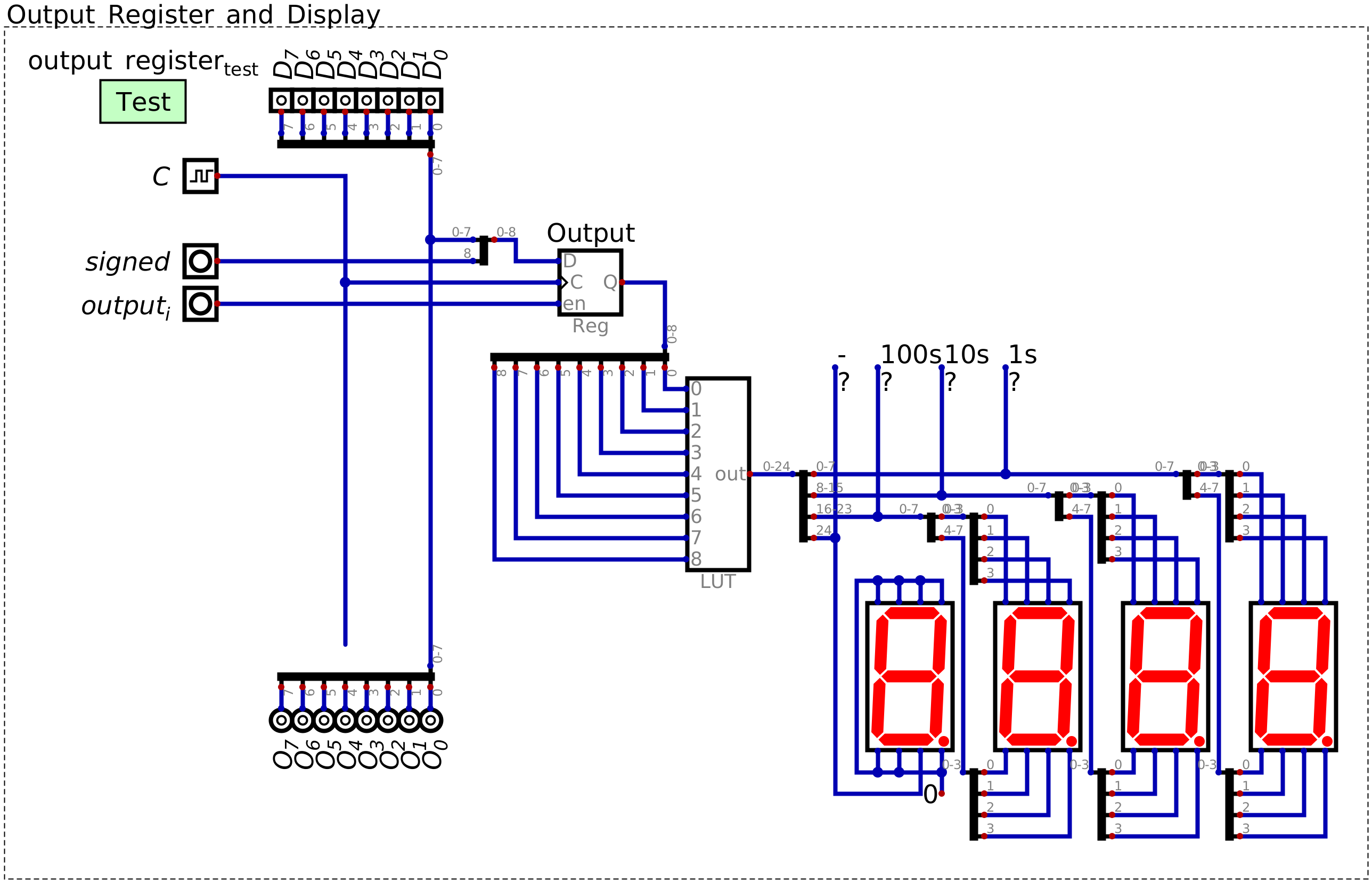
A register is added to the LUT and seven segment displays to create the output module for the system.
With this design, one can control when the data is loaded into the output register for displaying
As discussed in the previous topic, the \(signed\) signal controls when to output two’s complement numbers
Remember, this signal is ultimately an input signal like the other 8 input signals to the LUT
However, it effectively controls which block of 256 values are addressed by the 8 bits from the output register
When the signal is low, the 8 bits from the output register address 0 – 255
When the signal is high, the 8 bits from the output register address 256 – 511
It is important that the \(signed\) control signal is included in the output register as a ninth bit
For the same reason that the registers exist to store the data and separate it from the data bus
Otherwise, when the control signals on the control bus change, the state of the input to the LUT would change
The \(signed\) signal would likely go low, meaning that a signed int would be output as an unsigned int
However, remember that this ninth bit is not part of the data to be output, but storing the unsigned/signed state
16.2. Including Output in the System
Adding the output module to the ESAP system is an exercise in connecting the corresponding components
Like when adding the RAM module to the system
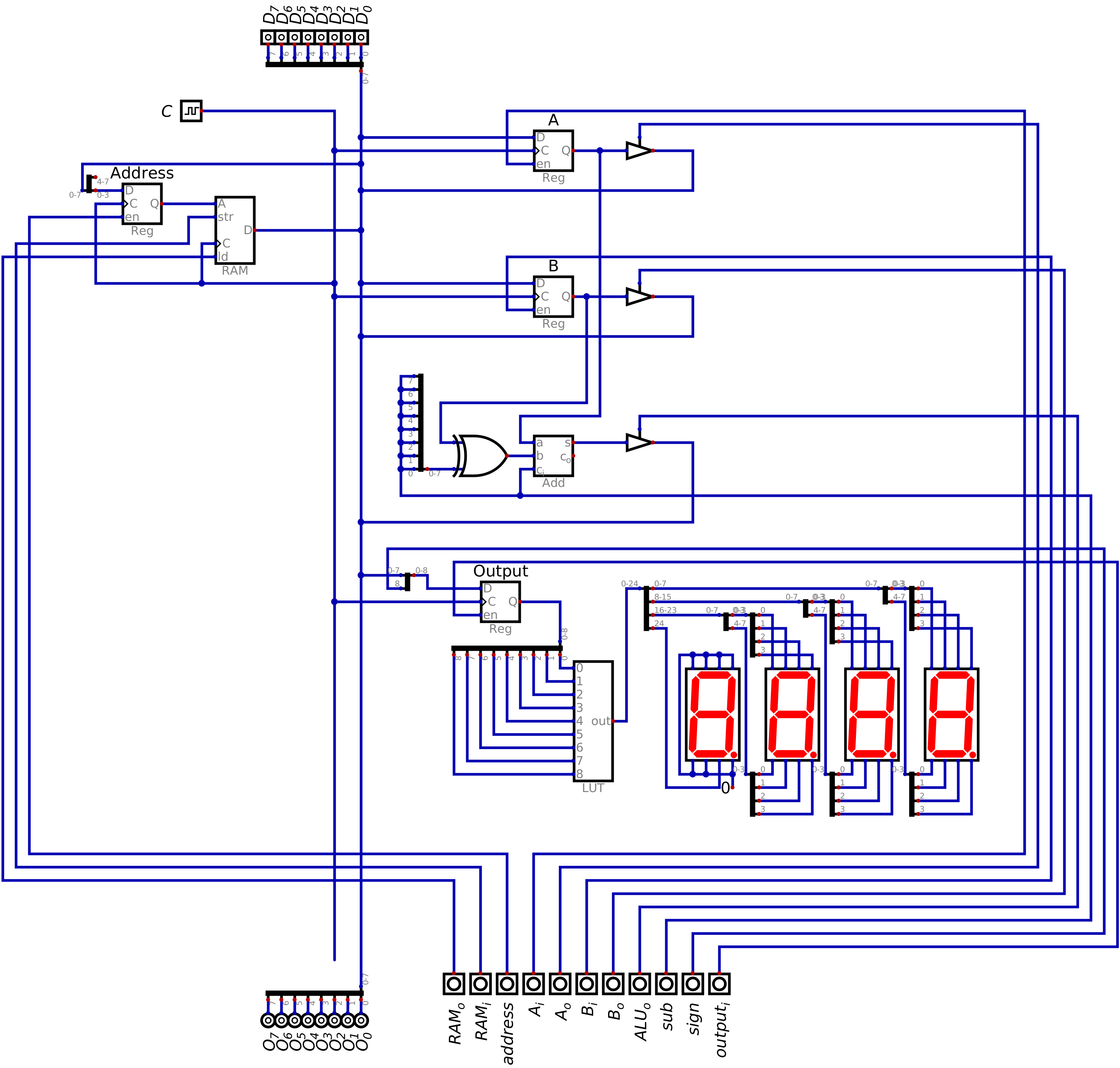
Configuration of the ESAP system with the ALU, RAM, and output modules connected.
Like before, the control signals are moved to the bottom of the design to keep them together
The placement of the output register in the ESAP system is not important, but does match the architecture overview
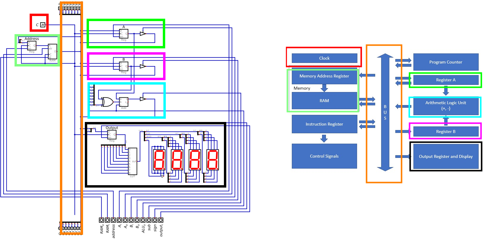
Comparison of the current system and the ESAP architecture overview.
16.3. Example of Outputting from the System
Like previous examples, the numbers 15 and 4 will be added together, but this time the result will be output
A simpler version of the program will be implemented here
Load 15 into A
Load 4 into B
Output the sum to the output register
The below table shows the control logic configuration to execute this program
The address register and RAM in/out are excluded for space
\(A\) |
\(B\) |
\(ALU_{o}\) |
\(sub\) |
\(out_{i}\) |
\(sign\) |
\(D\) |
\(C\) |
||
|---|---|---|---|---|---|---|---|---|---|
|
|
|
|
|
|
|
|
||
|
|
|
|
|
|
|
|
||
|
|
|
|
|
|
|
|
The below image shows the state of the system after adding 15 and 4 together and outputting the result
Due to the output register, the computer could continue to operate while still outputting this value
In other words, the control signals could change, along with the data on the bus, and the output would remain
Unless new data was put into the output register
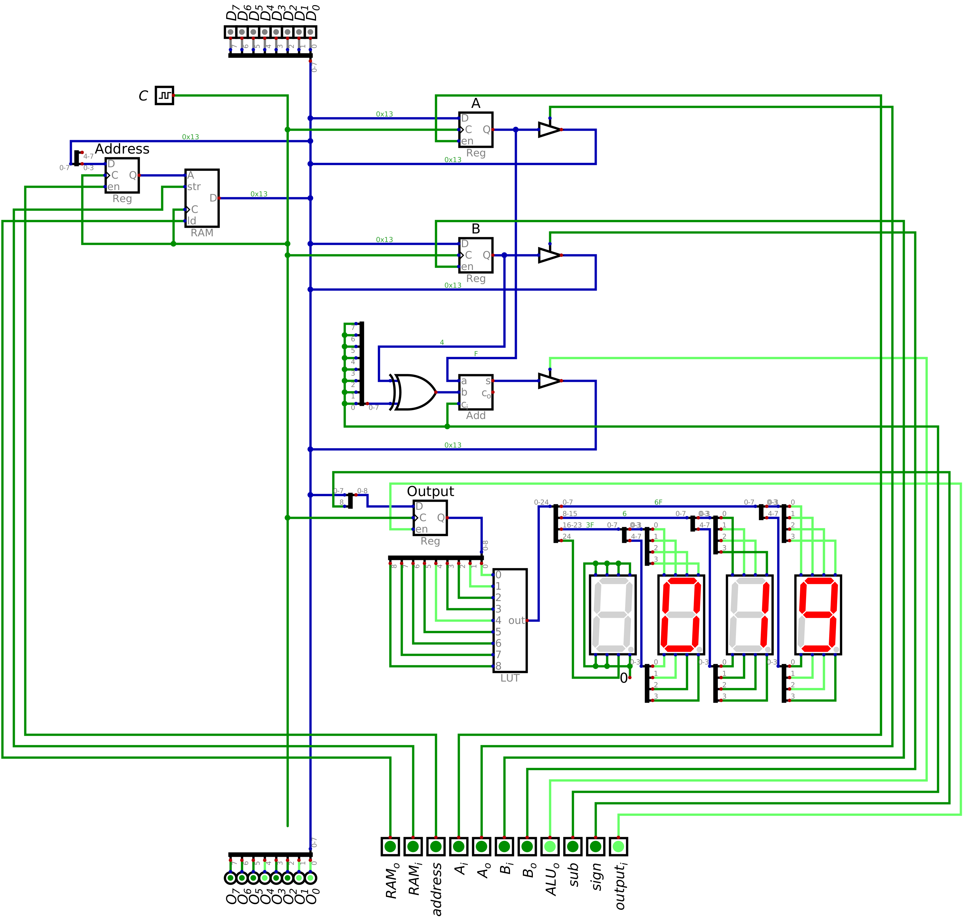
ESAP system outputting 19 on the seven segment displays. This would be the final state of the system after executing the program described in the above table.
16.4. For Next Time
Something?