21. Conditions
Although the system is programmable, it currently has a significant limitation
To highlight this limitation, consider the problem the following problem
Given some number, output
1if it is less than10, otherwise, output0
It turns out that it’s not possible as there is no way to check a condition
Think
Ifstatements
21.1. Conditional Jump Command
Consider the general idea of a program to check if a value is less than
10Load value into register A
If register A’s value is
< 10Output
1Halt
Otherwise
Output
0Halt
Currently there is no way to have a program branch based on a condition
There is no
ifstyle instruction
However, the current instruction set does include a jump instruction, which does provide some way to move around RAM
Therefore, using the idea of a jump, the program can be reframed
Load value into register A
If register A’s value is
< 10, jump to a part of RAM containing the following instructionOutput
1Halt
Otherwise
Output
0Halt
 1v2.0 raw
 20x1F (load data from address 0xF into A)
 30x?4 (Jump to address 0x4 if < 10)
 40xDD (Output 0)
 50xF0 (Halt)
 60xDE (Output 1)
 70xF0 (Halt)
 80x00
 90x00
100x00
110x00
120x00
130x00
140x00
150x00 (0 to output if not < 10)
160x01 (1 to output if < 10)
170x?? (some number to check)
Unfortunately, the jump instruction available in the current instruction set always jumps
There is no condition
However, there is room to add to the instruction set
Therefore, consider how this conditional jump idea could be done
What should the condition be?
How should the system handle it?
Having a jump for a specific condition and value like
< 10will work in this case, but it is not generalInstead, one could checks for
== 0or< 0as they are far more general and usefulFor example, if one wants to check if some value is
< 10, simply check the differenceIf
(value - 10) < 0, thenvalue < 10
Note
Technically, the system only needs the ability to check 1 condition to be functionally complete. For example, only having the ability to check if a value is 0 would be enough for a system like this to compute anything computable.
However, consider the number of steps required to check if a number is less than 10 with only the ability to check
if some value is == 0 versus the ability to check more conditional cases, like < 0.
Therefore, to increase flexibility and ease of programming, several conditions will be included in the ESAP system.
Since the ESAP system is only 8 bits and overflows may be common, a check for an overflow may also be helpful
Therefore, three conditions are to be included
If some value is 0
If some value is less than zero (negative)
If an overflow happened
Checking an overflow is a little trickier than the other conditions
To check if a value is
== 0or< 0, look at the valueHowever, one cannot look at an 8 bit value and know if an overflow happened
Instead, an overflow would have had to happen as the result of some arithmetic
Check the carry out of the adder
In fact, all three conditions can be checked when some arithmetic
Is the result of the arithmetic
== 0?Is the result
< 0?Did it cause an overflow?
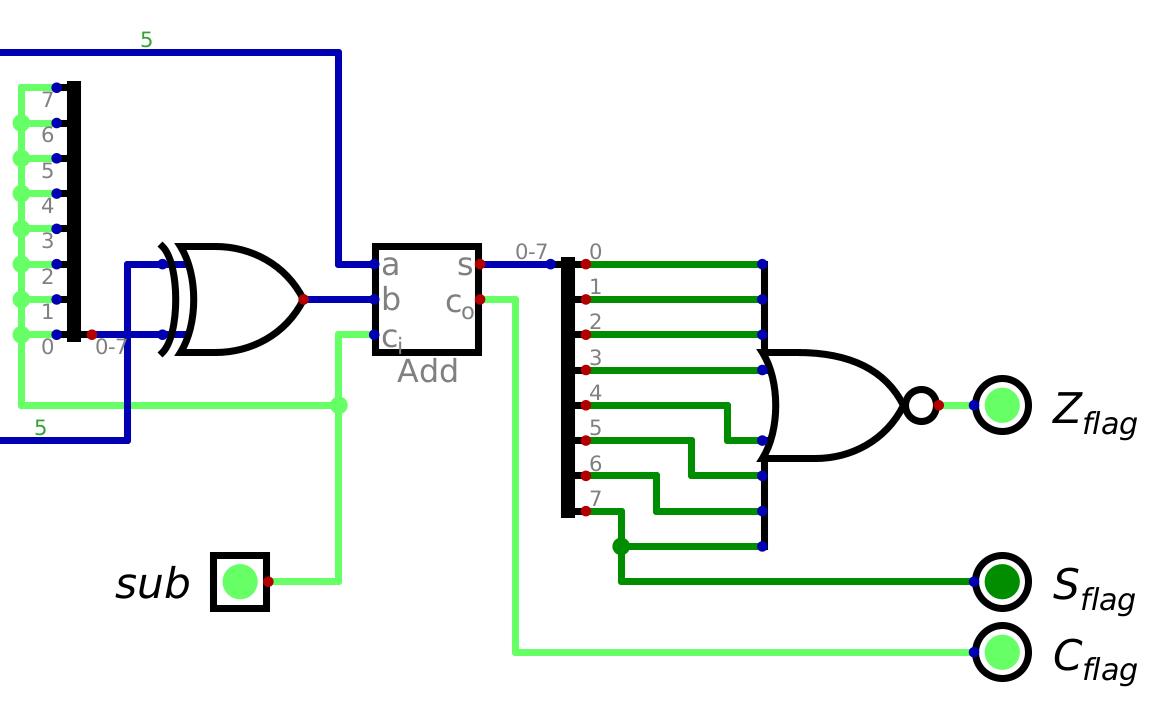
Looking back at the ALU designs discussed, notice that they have more than one output signal
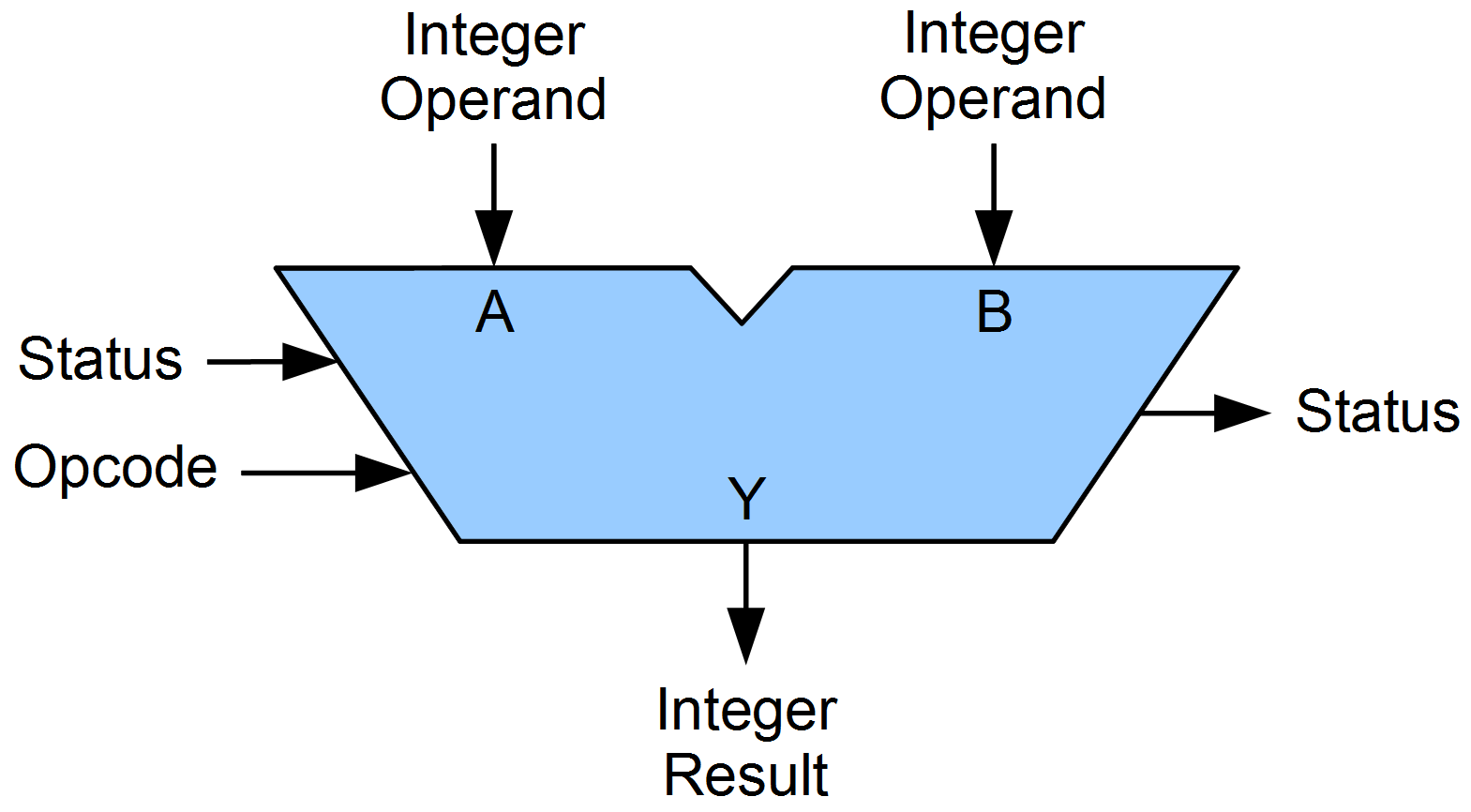
Generic symbol for an ALU. Notice “Status” out.
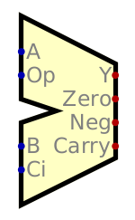
Digital’s importable ALU. Notice the three output signals labelled “Zero”, “Neg”, and “Carry”.
It is now a matter of building the hardware for the system to check these conditions
21.1.1. Status Flags
Checking if a value is zero is a matter of checking if all the bits are
0This can be done in several ways, but perhaps the easiest is with
NORThink of the
NORoperator’s truth table — only1when all inputs are0
Checking if a number is negative is a little tricky because it requires one to know if the integer is signed or not
If it’s a signed integer, and the most significant bit is a
1, then the number is negativeIf it’s an unsigned integer, then the value cannot be negative
It would be the responsibility of the programmer to know if the data is signed as the system itself does not know
Remember, the bits are an encoding of some data
The meaning of data depends on what is being encoded/how it should be decoded
Therefore, all the system can do is check the signal on the most significant bit
Then the programmer, knowing the context in which they are using the system, can use this information
Finally, knowing if an operation resulted in an overflow/carry is a matter of checking the carry signal from the adder
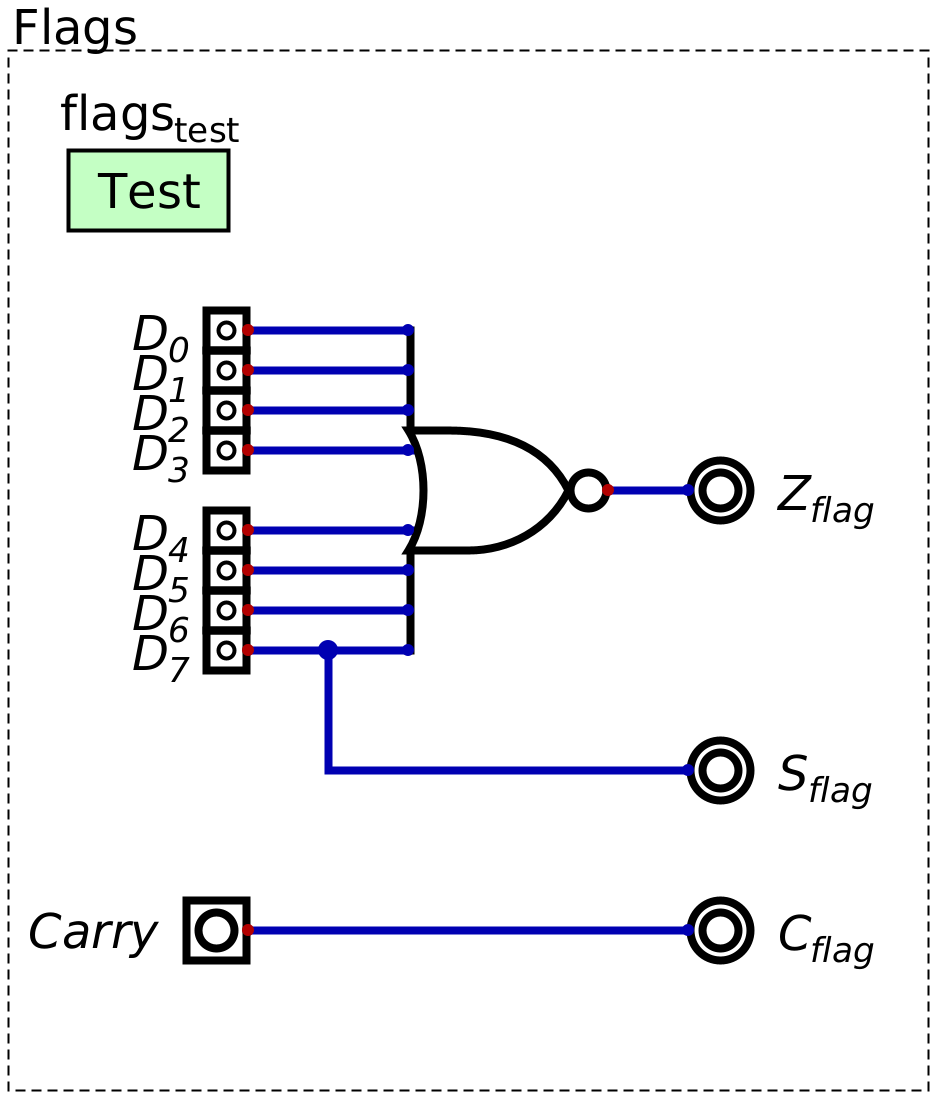
Logic to check the various states. The \(Z_{flag}\) is a signal indicating if some value is zero, \(S_{flag}\) indicates if the most significant bit is high (which can be used to check if a value is negative), and \(C_{flag}\) indicates if the carry bit is high. This \(C_{flag}\) signal would be connected to the adder’s carry out signal.
21.2. Flags Register
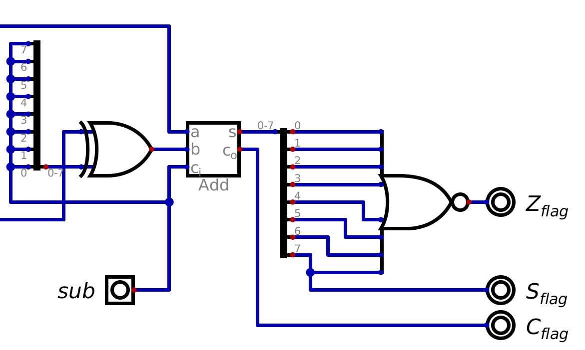
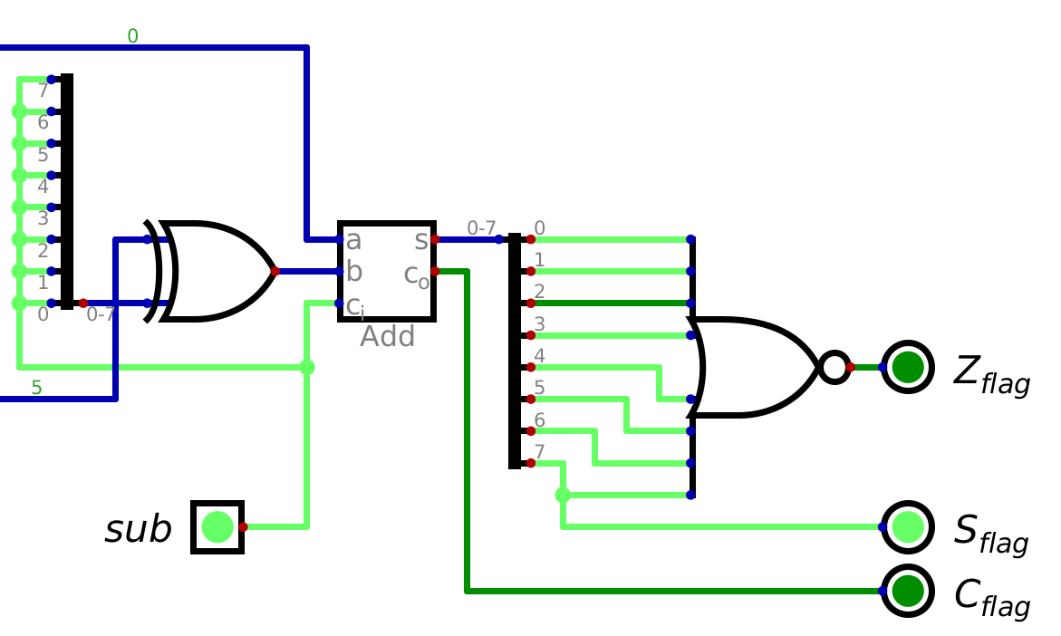
Status flag signals connected to an ALU. The output of the ALU would typically be sent back to the data bus, but here the output is ignored except for analysing the output’s status for the purpose of determining the status flags.
The goal is to know if the last arithmatic operation performed caused any of the status signals to change
However, the adder is always outputting a value based on the contents of registers A and B
This is true, even when addition/subtraction is not intentionally being performed
For example, consider the steps the system performs when calculating
5 - 5Load
5into ALoad
5into BSet the subtraction signal
At this instant, the status flag signal \(Z_{flag}\) should be
1The overflow will also be high too, as a consequence of 2s compliment arithmetic
Put value from ALU into A
At this instant, the status flag signal \(Z_{flag}\) would change to
0This is because the adder always calculates the sum/difference of the values in registers A and B
Therefore, since the ALU is outputting
-5, the zero flag is low, but the significant/sign flag is highThis second calculation was unintended and a consequence of the design of the system
Status flag signals after the ALU calculates 5 - 5, but before the output of the ALU is sent back into register
A. Notice that the zero flag is high, since 5 - 5 = 0.
Status flag signal after the result of 5 - 5 (0) is placed into register A. Since the ALU is always
calculating the difference of the current values in registers A (now 0) and B (5), the value being output by
the adder component will be (5 - 5) - 5, or -5. Because of this, the zero flag is no longer high, even
though the last subtraction operation did result in a 0.
The status signals are always changing, but these status signals are to be known at very specific times
As a result of the last operation
For example, when the intended
5 - 5was computed, not the subsequent unintended operation
In other words, there needs to be a way to preserve the status flag values when specific operations are done
Like before, this can be achieved with a register — a flag register
The key is to carefully control when the register’s inputs, the status flag signals, are actually stored
Only enable the flag resister to store the signals when performing addition or subtraction
In all other cases, the value being output by the adder component does not matter
With this, all condition checks are based on the last arithmatic operation performed
The zero, significant/sign, and carry conditions
Below is an example of an adder with logic for the status flag signals being fed into a flag register
Here, except for the status flags logic, the value of the output of the adder is ignored
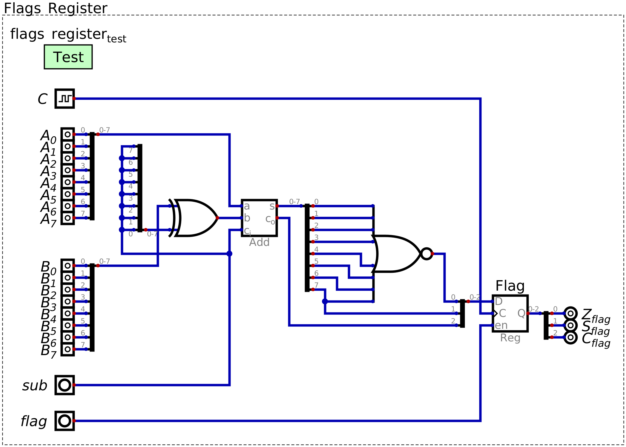
Configuration of an adder component with a status flag register. This design contains the logic to determine if any of the three status signals should be high based on the output of the adder. The value of the status signals can be latched into the flags register for later use.
21.3. For Next Time
Something?