22. Conditional Jump Instructions
The various status flag values can now be determined and stored in the flags register
However, how should the conditional jumps be handled by the control logic?
Further, the existing control logic needs to be updated to now handle the new flag register control signal
When should the system’s status signal values be stored stored in the flags register?
22.1. Conditional Jump Control Logic
The conditional jumps allow the program to jump to different parts of the program based on some condition
More specifically, when some status flag is high, the conditional jump updates the program counter’s value
The program counter is updated to contain a new memory address — the address of the new next instruction
In the same way as the jump always instruction
For example, consider a jump zero command —
JMPZIf the zero status flag is high, update the program counter with some specified memory address
If the status flag is low, ignore and carry on
Notice that this instruction has two cases
Two versions of the instruction that can be performed
The control logic for the two versions of the instruction effectively already exists
The jump version control logic is the same as the
JMPAinstructionFetch cycle
Move operand (memory address to jump to) out from the instruction register into the program counter
The ignore version is a
NOOPFetch cycle
Nothing
What does not exist is a way to select which version of the instruction to perform
The jump, or the
NOOPversion
22.1.1. Controlling the Cases
If the status flags store their respective conditions, they indicate which version of the conditional jumps to perform
For example, if the \(Z_{flag}\) signal is high, perform the jump version, if it’s low, perform
NOOP
The same idea used for dealing with the output register’s unsigned/signed cases can be used
Multiple look up tables with a multiplexer could be used
Or, a single, larger, look up table with additional input signals can be used
With this idea, the status flags can be input into the control logic’s look up table
This results in a total of 9 inputs

The 9 bit input to the look up table broken down into the three parts — flags, operator, and microcode counter.
The most significant 3 bits, CSZ correspond to the status flags (carry, significant/sign, zero), the next 4 bits
specify an instruction’s operator XXXX, and the final 2 bits YY are the microcode step, from the microcode
counter.
Like before, different segments of the input to the look up table have different meaning
The lest significant 2 bits correspond to the microcode counter
The next 4 bits correspond to the specific instruction
The additional 3 bits, the most significant bits, correspond to the status flags
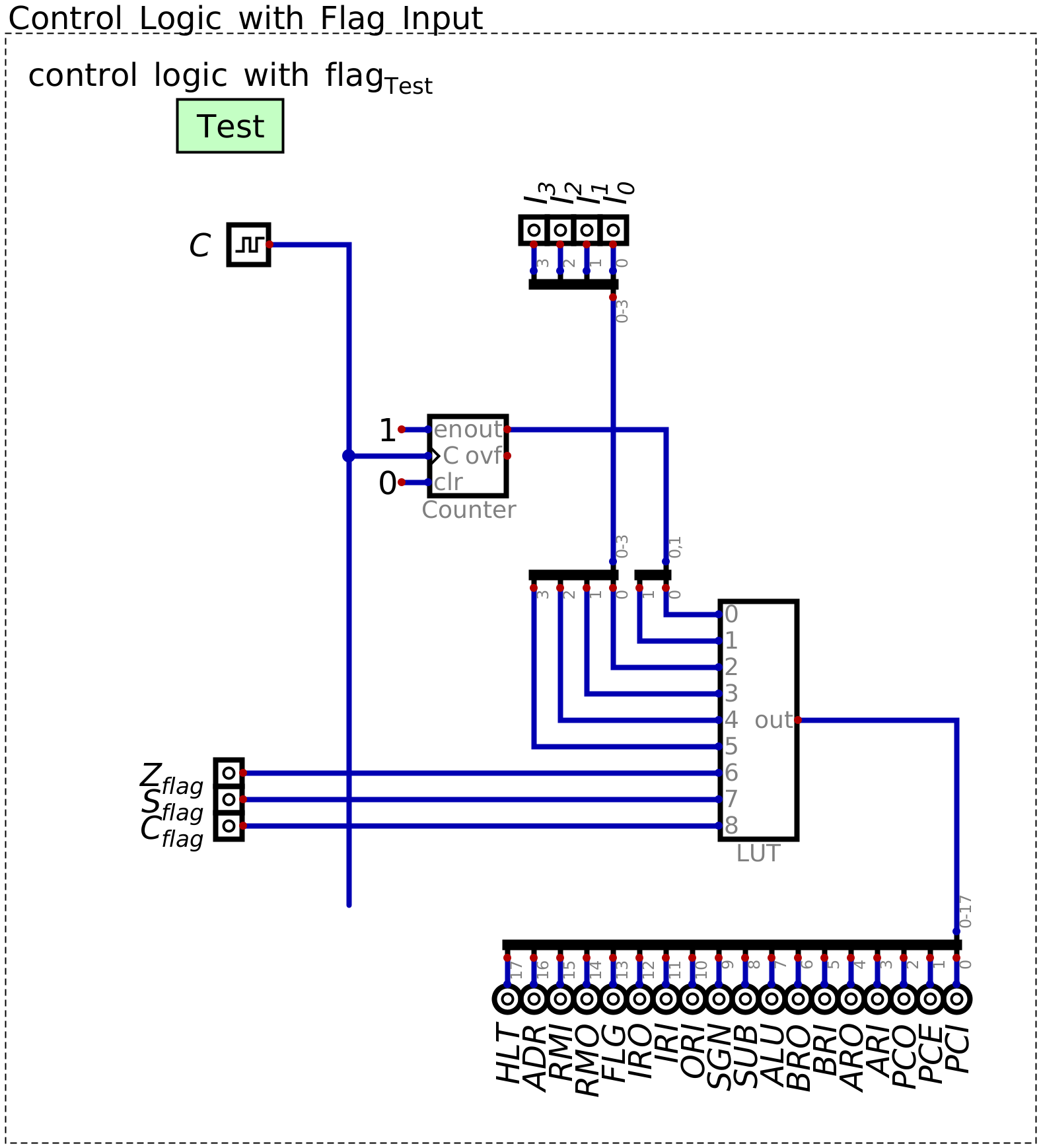
Design of the look up table with the status flag signals included as inputs. This design has a total of 9 signals
serving as inputs to the look up table — 3 for the status signals, 4 for the instruction’s operator, and 2 for
the microcode step. Notice the FLG control signal on the output from the look up table — this controls when
the flags register is enabled.
Since there are an additional 3 input bits, the size of the look up table grows by eight times
Eight segments of 16 instructions
Each of the eight segments of the look up table corresponds to how the instructions should work given the status flags
However, of the 16 instructions, only the 3 conditional jumps will be different, depending on the status flags
With this design, it means that there will be a lot of redundant, duplicate control logic
But it will make the implementation simple
With this design in mind, there still needs to be control over when the flags register is enabled
22.2. Enabling Flag Register
As discussed, the status flag register needs to be enabled at specific times to work
Only enable when performing addition or subtraction
Disabled at all other times
However, both addition and subtraction take several clock cycles
Every instruction is allocated 4 clock cycles
Although, addition (
ADAB) and subtraction (SUAB) only require 3Fetch (2 clock cycles)
Output from ALU to the A register, and set the subtract signal where necessary (1 clock cycle)
Therefore, the question is, when exactly should the flag enable signal be set high?
It does not make sense to do it during the two clock cycles of fetch
All fetch cycles should be the same
Has nothing to do with the underlying instruction
It could work during the ALU -> A register step
At this instant, the value the ALU has is the value to be calculated
Therefore, the status flags at this time are relevant to the instruction
It would not work after the ALU -> A step
The value in the A register would be change after the ALU -> A step
This means the status flags may have changed
For example, performing
5 - 5If A is
5and B is5before subtraction, the ALU calculates0, and theZflag is highAfter the ALU -> A step, A now stores
0, meaning the ALU calculates0 - 5, andZis now low
Therefore, the flag register enable should be high at the time that the ALU is being output
Note
One may wonder — is it possible for the value from the ALU to be latched into A, thereby altering the status signals, before the value of the status signals can be latched into the flags register?
This is not an unreasonable question to ask, and can be addressed by making the addition and subtraction instructions take four clock cycles by adding a new microinstruction after the fetch cycle, but before the ALU -> A step:
Fetch (2 cycles)
Set subtract if necessary and store the status signals (1 cycle)
Set subtract if necessary and ALU -> A (1 cycle)
However, this is not a real concern given the synchronization of the system. Within Digital, values are latched into the registers the instant the clock signal goes high. In practice, there would be some delay due to the physical limitations of the hardware, but any delay on latching a value into the flags register would be less than the total delay of latching a value into the A register, outputting from the A register, moving to the ALU, and moving through the ALU.
22.3. Including the Flag Register in the System
Physically including the status logic and the flags register is a matter of connecting it to the existing system
Connect the output of the ALU to the input of the condition status logic
Replace the old control logic look up table design with the new one
The 3 output from the flags register are connected to the inputs to the look up table
The 1 new output from the look up table connects to the status flag register’s enable
Notice the cycle — the flags register controls the control logic, which controls the flags register
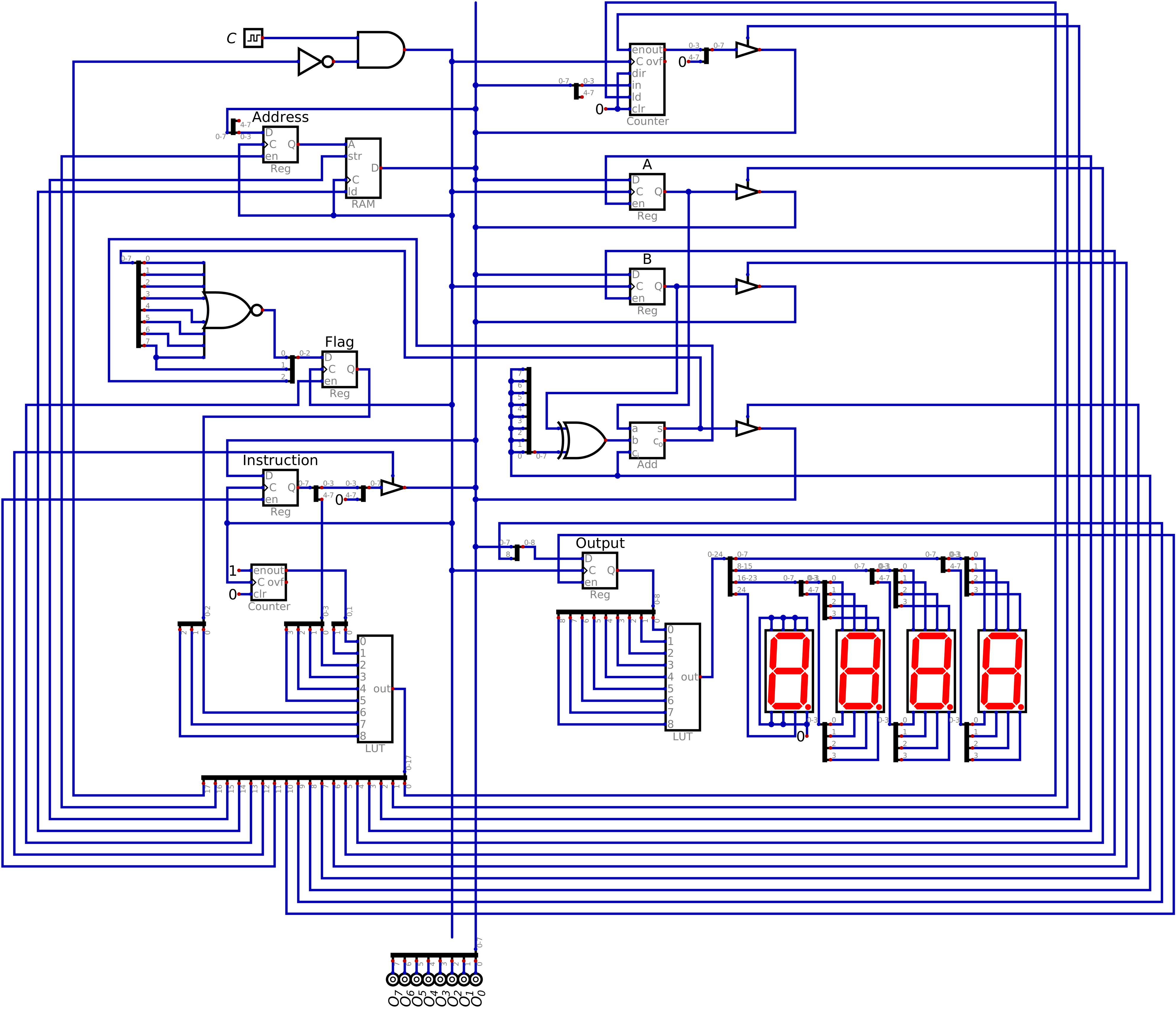
Configuration of the ESAP system with the status condition logic and the flags register included. The ESAP system is now computationally complete.
22.3.1. Updating the Look Up Table Contents
The contents of the look up table needs to be updated to account for the changes
Three new commands for the three different conditional jumps
Three new status signals serving as inputs to the look up table
An additional output signal from the look up table
A modified version of the script used before to generate the hex file for the look up table is used
Like before, below are constants specifying the position of the control signal’s bit
Here, there are a total of 18 bits, which is one more than before
This corresponds to the control signal for the status flag register enable
38HLT = 0b10_00000000_00000000
39ADR = 0b01_00000000_00000000
40RMI = 0b00_10000000_00000000
41RMO = 0b00_01000000_00000000
42FLG = 0b00_00100000_00000000
43IRO = 0b00_00010000_00000000
44IRI = 0b00_00001000_00000000
45ORI = 0b00_00000100_00000000
46SGN = 0b00_00000010_00000000
47SUB = 0b00_00000001_00000000
48ALU = 0b00_00000000_10000000
49BRO = 0b00_00000000_01000000
50BRI = 0b00_00000000_00100000
51ARO = 0b00_00000000_00010000
52ARI = 0b00_00000000_00001000
53PCO = 0b00_00000000_00000100
54PCE = 0b00_00000000_00000010
55PCI = 0b00_00000000_00000001
Since the jump instructions are special, their operator bit patterns will be made constants
62JMPA = 0b1001
63JMPZ = 0b1010
64JMPS = 0b1011
65JMPC = 0b1100
Similar to before, the microcode instructions are stored in a list
The specific microcodes for each instruction are created with bitwise OR on the control signal constants
The difference here versus before is
The inclusion of the
FLGsignal on the addition and subtraction instructionsThe labelling of
JMPZ,JMPS, andJMPCinstructionsNotice that they are still effectively
NOOPinstructions hereThis will be their default behaviors
Only under the special conditions do they act like jump instructions
72INSTRUCTIONS = [
73    [PCO|ADR,   RMO|IRI|PCE, 0,               0           ],  # 0b0000 --- 0x0 --- NOOP --- No Operation
74    [PCO|ADR,   RMO|IRI|PCE, IRO|ADR,         RMO|ARI     ],  # 0b0001 --- 0x1 --- LDAR --- Load A From RAM
75    [PCO|ADR,   RMO|IRI|PCE, IRO|ARI,         0           ],  # 0b0010 --- 0x2 --- LDAD --- Load A Direct
76    [PCO|ADR,   RMO|IRI|PCE, IRO|ADR,         RMO|BRI     ],  # 0b0011 --- 0x3 --- LDBR --- Load B From RAM
77    [PCO|ADR,   RMO|IRI|PCE, IRO|BRI,         0           ],  # 0b0100 --- 0x4 --- LDBD --- Load B Direct
78    [PCO|ADR,   RMO|IRI|PCE, IRO|ADR,         ARO|RMI     ],  # 0b0101 --- 0x5 --- SAVA --- Save A to RAM
79    [PCO|ADR,   RMO|IRI|PCE, IRO|ADR,         BRO|RMI     ],  # 0b0110 --- 0x6 --- SAVB --- Save B to RAM
80    [PCO|ADR,   RMO|IRI|PCE, ALU|ARI|FLG,     0           ],  # 0b0111 --- 0x7 --- ADAB --- Add B to A
81    [PCO|ADR,   RMO|IRI|PCE, ALU|SUB|ARI|FLG, 0           ],  # 0b1000 --- 0x8 --- SUAB --- Subtract B from A
82    [PCO|ADR,   RMO|IRI|PCE, IRO|PCI,         0           ],  # 0b1001 --- 0x9 --- JMPA --- Jump Always
83    [PCO|ADR,   RMO|IRI|PCE, 0,               0           ],  # 0b1010 --- 0xA --- JMPZ --- Jump Zero
84    [PCO|ADR,   RMO|IRI|PCE, 0,               0           ],  # 0b1011 --- 0xB --- JMPS --- Jump Significant/sign
85    [PCO|ADR,   RMO|IRI|PCE, 0,               0           ],  # 0b1100 --- 0xC --- JMPC --- Jump Carry
86    [PCO|ADR,   RMO|IRI|PCE, IRO|ADR,         RMO|ORI     ],  # 0b1101 --- 0xD --- OUTU --- Output Unsigned Integer
87    [PCO|ADR,   RMO|IRI|PCE, IRO|ADR,         RMO|ORI|SGN ],  # 0b1110 --- 0xE --- OUTS --- Output Signed Integer
88    [PCO|ADR,   RMO|IRI|PCE, HLT,             0           ],  # 0b1111 --- 0xF --- HALT --- Halt
89]
The above 16 instructions are how the instructions should work when none of the status flags are high
However, the conditional jumps need to work differently depending on the status flag signals
As discussed, each row/individual microcode is accessed by some input patter in the look up table
With this new design, the 3 most significant bits correspond to the status flag signals
CSZ|XXXX|YYFlags|Instruction|Step
The above list of 16 instructions and microcodes correspond to the first set of 16, when no status signals are high
000|XXXX|YY
The pattern of 16 instructions and microcodes will be repeated 8 times
Once for each combination of the status signals being high
000— No flags001— Zero flag set010— Significant/sign flag set011— Significant/sign and zero flags set100— Carry flag set101— Carry and zero flags set110— Carry and significant/sign flags set111— Carry, significant/sign, and zero flags set
For each of the 8 groupings, the conditional jumps will act as a jump when the respective status signal is high
Otherwise, it acts as a
NOOP
121with open("control_logic_with_flag_patterns_for_look_up_table.hex", "w") as hex_file:
122    hex_file.write("v2.0 raw\n")
123    for flags_state in range(8):
124        for i, instruction in enumerate(INSTRUCTIONS):
125            if (i == JMPZ and flags_state & 0b001 != 0 or
126                    i == JMPS and flags_state & 0b010 != 0 or
127                    i == JMPC and flags_state & 0b100 != 0):
128                # If special jump instruction and the flag is set, do jump instruction microcodes
129                hex_file.writelines(f"{hex(microcode_pattern)}\n" for microcode_pattern in INSTRUCTIONS[JMPA])
130            else:
131                hex_file.writelines(f"{hex(microcode_pattern)}\n" for microcode_pattern in instruction)
This checks if the current instruction is a conditional jump and if the corresponding status flag is high
When this is the case, act as a jump instruction
Otherwise, use the default behaviour
This script would generate the new contents for the control logic’s look up table
This hex file is to be loaded into the system’s new look up table
With this updated control logic, the system now has the ability to branch on conditions
22.4. Programming with Conditional Jumps
With this new functionality, conditional jumps, branching can now be achieved
Consider the problem discussed before
Given some number, output
1if it is less than10, otherwise, output0
This problem can be solved with the following general idea
Load value into register A
Subtract
10from the valueIf the result is negative (the most significant bit is high), the value must be
< 10
If the result is negative, jump to a part of RAM that outputs
1JMPS
If the result is not negative, output
0
Below is the ESAP system’s machine code for the above idea
The emphasized line contains the conditional jump for the significant bit/sign flag
Here, the value in RAM address 15 is the number to check
 1v2.0 raw
 20x1f
 30x4a
 40x80
 50xb6
 60xdd
 70xf0
 80xde
 90xf0
100x00
110x00
120x00
130x00
140x00
150x00
160x01
170x05
Unfortunately, the machine code in hex format is hard to interpret
To make this more human readable, the program can be explained as follows
 1Load the value from address 15 to register A
 2Load the value 10 to register B
 3Calculate the difference
 4Jump to address 6 if the significant bit/sign flag is high
 5Output the contents of RAM address 13
 6Halt
 7Output the contents of RAM address 14
 8Halt
 9NOOP
10NOOP
11NOOP
12NOOP
13NOOP
140
151
16Number to check
22.5. For Next Time
Something?